Building a medical device for the Hackster.io Arduino UNO Q contest means working with whatever parts you can actually get your hands on. In practice, that means cheap AliExpress modules, and cheap AliExpress modules do not always behave the way the listing describes.
Two components burned the most time on this build before I wrote any application code: the MAX30102 pulse oximeter and the 128×64 OLED display. Both looked fine on the bench. Both had hardware-level problems that no tutorial warned me about. Here is what went wrong and how I fixed each one.
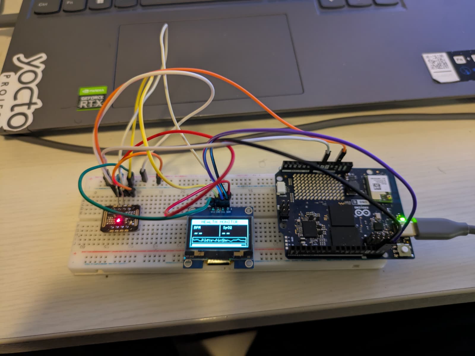
Part 1. MAX30102: a silent sensor on a healthy I2C bus
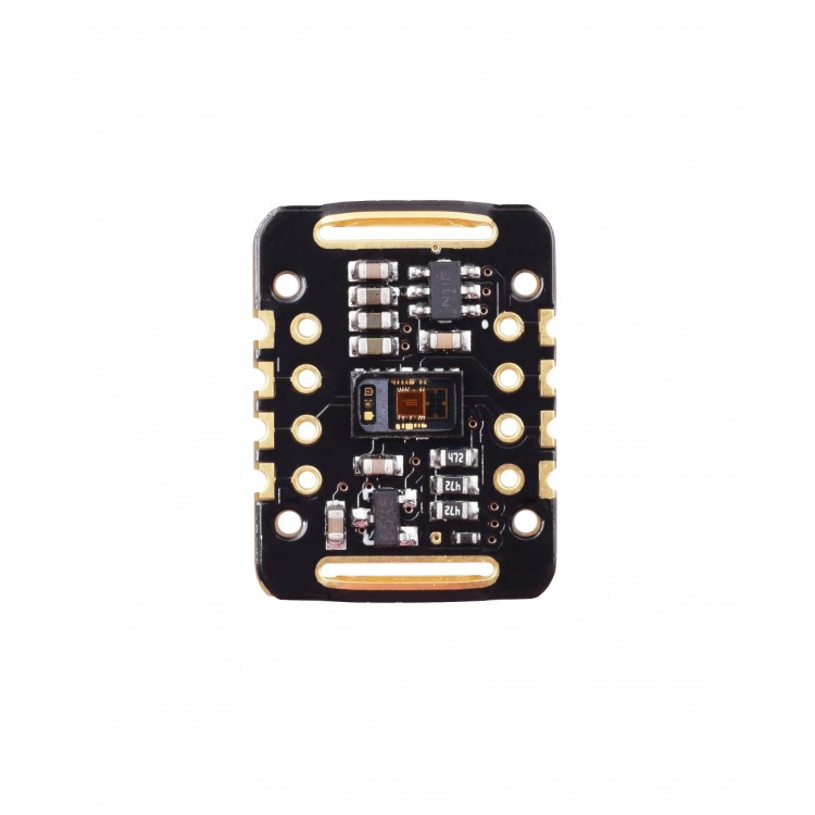
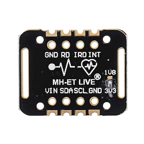
Symptom
I wired the MAX30102, flashed a standard I2C scanner, and got this:
I2C Scanner...
Scan done.
Zero devices. The MAX30102 should appear at address 0x57. It did not.
The OLED on the same bus responded correctly at 0x3C, so the bus itself was alive. Pull-ups, clock, ground, all fine for the display. The problem was specific to the MAX30102 module.
Every YouTube tutorial I had followed showed the sensor working on the first try. Mine did not. The tutorials were not wrong; their modules were simply not the one I had.
Root cause
A significant share of the MAX30102 (and MAX30100) modules sold cheaply on AliExpress ship with a PCB-level fault: the I2C pull-up resistors on the breakout are tied to the wrong rail, so SDA and SCL sit at a voltage the microcontroller cannot reliably read as logic high. The chip is powered. The chip is running. It simply cannot talk to the MCU at the expected levels.
This is documented in detail here, and I strongly recommend reading it before you start:
reedpaper.wordpress.com, Pulse Oximeter MAX30100 / MAX30102: how to fix wrong board
The article covers the exact PCB trace to cut if you want the permanent hardware fix.
Fix
The fastest workaround, with no soldering required, is to add external pull-ups on the breadboard:
- One 4.7 kΩ resistor from 3.3 V to SDA
- One 4.7 kΩ resistor from 3.3 V to SCL
Colour code for 4.7 kΩ: yellow, violet, red, gold.
Other things that matter on this module:
- Power it from 3.3 V, not 5 V. The breakout has a regulator on some revisions and none on others. 3.3 V is always safe.
- Keep jumper wires short, under roughly 10 cm. Long wires on a weakly-driven I2C bus are where marginal setups become unreliable setups.
With the external pull-ups in place, the scanner found the sensor at 0x57 immediately, and it has been stable since.
Part 2. OLED display: SSD1306 code on an SH1106 controller
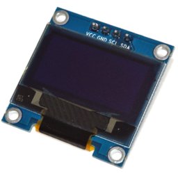
Symptom
I ordered a 128×64 OLED module listed as an SSD1306. The I2C scanner detected it at 0x3C, so communication was working. I then flashed a sketch using the standard SSD1306 Arduino library.
The screen stayed blank. No output at all.
Assuming the SSD1306 library was the issue, I switched to U8g2, which supports a much wider range of displays. The screen came alive, but something was clearly off. Text appeared, but characters were cut off at the edges, and the whole layout was shifted a few pixels in one direction. A classic rendering-offset symptom.
I had made a subtle mistake: I had initialised U8g2 with the SSD1306 constructor, because that is what the seller had listed.
Root cause
The module was not an SSD1306. It was an SH1106.
The SH1106 is a different OLED controller that shares the SSD1306's physical form factor, resolution, and I2C address, but uses a different internal memory map. The two chips are visually indistinguishable on the outside of the module, which is why AliExpress sellers routinely list SH1106 boards as SSD1306. Most buyers never drive the display hard enough to notice.
Because I was using the SSD1306 constructor in U8g2, the library was sending SSD1306-style column addresses to an SH1106 display. The display partially obeyed, enough to draw pixels on screen, but offset by the few columns of RAM that SH1106 reserves differently from SSD1306. Hence the shift and the clipping.
Fix
One line of code. Change the constructor:
// Before (wrong for this module)
U8G2_SSD1306_128X64_NONAME_F_HW_I2C u8g2(U8G2_R0, U8X8_PIN_NONE);

// After
U8G2_SH1106_128X64_NONAME_F_HW_I2C  u8g2(U8G2_R0, U8X8_PIN_NONE);
Everything else in the sketch stays the same. U8g2 handles the SH1106 memory mapping internally, and the output snaps into perfect alignment.
How to check which controller you actually have: load a minimal sketch that draws a short string starting at x = 0. Try the SSD1306 constructor, then the SH1106 constructor. The correct one is whichever renders the text cleanly against the left edge with no clipping.
Why U8g2 is worth using anyway
Even if the seller's listing had been accurate, I would have moved to U8g2:
- It supports over 100 display controllers behind a consistent API, so a mislabelled or swapped module becomes a one-line change instead of a rewrite.
- It ships with a large built-in font library at multiple sizes.
- It flushes the display buffer atomically, which eliminates the flicker you get when refreshing live sensor data every second. Important for a medical UI.
Takeaway
Both problems had the same underlying cause: AliExpress modules that do not match their datasheet listing. One was a PCB-level fault on a genuine-ish MAX30102. The other was a different silicon die behind a familiar label. Neither is visible from the outside, and both first present as software or wiring bugs, which is exactly where you waste the most time looking.
If you are building anything remotely safety-adjacent on cheap modules, assume the listing is a starting hypothesis, not a spec sheet. Scan the bus. Check the logic levels with a scope or a logic analyser if you have one. Try more than one driver library. The half-hour you spend verifying the hardware up front is the half-day you do not spend debugging phantom application bugs later.
www.linkedin.com/company/ta-embedded/ · github.com/FrankApala