This is Part 2 of the Embedded Linux series. If you have not set up your cross-compilation toolchain yet, start with Part 1 first:
Embedded Linux Part 1 — How to Build an ARM Cross-Compiling Toolchain with Crosstool-NG
Once your toolchain is in place, come back here.
If you have ever tried to set up a proper embedded Linux boot chain on a Raspberry Pi 4, you know it is not as simple as flashing an image and pressing power. This post walks through the full process of building Trusted Firmware-A (TF-A) and U-Boot from source and booting the RPi4 with a real EL3 secure monitor, the same way production embedded systems work.
This is part of an ongoing series based on Bootlin's open-source Embedded Linux training, adapted for the Raspberry Pi 4. Every step was run on real hardware. Every error shown is one that was actually encountered. The goal is not just to provide commands to copy — it is to explain what each command does and why, so that when something breaks (and it will), you know where to look.
What you need before starting
- Raspberry Pi 4 Model B (any RAM size)
- MicroSD card, 8GB minimum
- USB to TTL serial adapter (3.3V logic level — CP2102 or CH340 work well)
- Ubuntu host machine (20.04 or later)
- AArch64 cross-compiler built in Part 1
Set up the cross-compiler path before anything else:
export PATH=$HOME/x-tools/aarch64-training-linux-musl/bin:$PATH
export CROSS_COMPILE=aarch64-linux-
Verify it points to the right compiler:
${CROSS_COMPILE}gcc --version
# aarch64-linux-gcc (crosstool-NG 1.28.0) 14.3.0
If that prints your host x86 gcc instead, the PATH is wrong. Fix it before continuing — every build step depends on this being correct.
Part A — Understanding the boot chain
A.1 Why bother with TF-A on RPi4?
Most RPi4 tutorials skip TF-A entirely. Copy a kernel8.img to a FAT partition, add a config.txt, and U-Boot starts. Simple.
But on a real embedded product — an automotive ECU, a medical device, a drone flight controller — TF-A is not optional. It provides three things that matter in production:
PSCI is the ARM standard for CPU power management. Without it, reboot and shutdown do not work correctly on ARM. The kernel calls into BL31 via SMC instructions whenever it needs to manage CPU power states.
CPU errata workarounds are silicon bug patches applied at EL3 before Linux runs. The Cortex-A72 has several known errata. TF-A applies the workarounds automatically during initialization.
Security services are the foundation for TrustZone and OP-TEE on production platforms. The Cortex-A72 does support TrustZone at the hardware level, but the Raspberry Pi firmware does not provide a full secure boot chain or enforce memory isolation between worlds. The RPi4 is unsuitable as a true secure platform, but it is the right board to learn the concepts and tooling that transfer everywhere else.
A.2 The RPi4 boot sequence
Before writing a single command, understand what is being built. The RPi4 boot sequence is unusual compared to most ARM SoCs:
Power on
    ↓
GPU ROM (VideoCore, on-chip)
    ↓
start4.elf                       ← GPU firmware, read from FAT partition
    ↓
armstub8.bin  (TF-A BL31 binary, renamed for GPU firmware)
                                 ← loaded to 0x0, executes at EL3
    ↓
kernel8.img   (U-Boot.bin, I renamed the U-boot binary to Kernel8.img)  ← loaded to 0x80000, runs at EL2
    ↓
Linux kernel                     ← loaded by U-Boot, runs at EL1
    ↓
User applications                ← EL0
On a classic ARM SoC like the STM32MP2, the CPU starts from BootROM and the firmware chain runs on the ARM cores from the first instruction. On the RPi4, the VideoCore GPU controls the entire boot process and only releases the ARM cores after loading everything into RAM. This distinction matters when debugging boot failures — errors that look like CPU problems are often GPU firmware issues.
Note on bootcode.bin: On Raspberry Pi 3 and earlier,
bootcode.binwas the second-stage GPU bootloader loaded from the SD card. On Raspberry Pi 4 this role is handled by a first-stage bootloader stored in on-board EEPROM, sobootcode.binis no longer required. The file is still present in official firmware packages for compatibility, but it does not affect a normal TF-A + U-Boot setup. Keeping it or removing it makes no difference.
To make the architectural difference concrete:
Classic ARM SoC (e.g. STM32MP2):
BootROM → TF-A BL1 → TF-A BL2 → BL31 → U-Boot → Linux

Raspberry Pi 4:
GPU firmware (start4.elf) → TF-A BL31 (armstub8.bin) → U-Boot → Linux
TF-A runs at EL3 and transitions the system to EL2 before handing control to U-Boot. U-Boot runs at EL2 and later boots Linux at EL1.
Part B — Setting up the serial console
Set up the serial console before anything else. This is the only window into the boot process. Every message from TF-A, U-Boot, and the Linux kernel appears here. Without it, debugging is guesswork.
B.1 Wiring the USB to TTL adapter
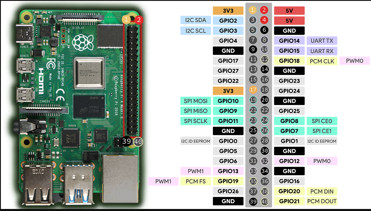
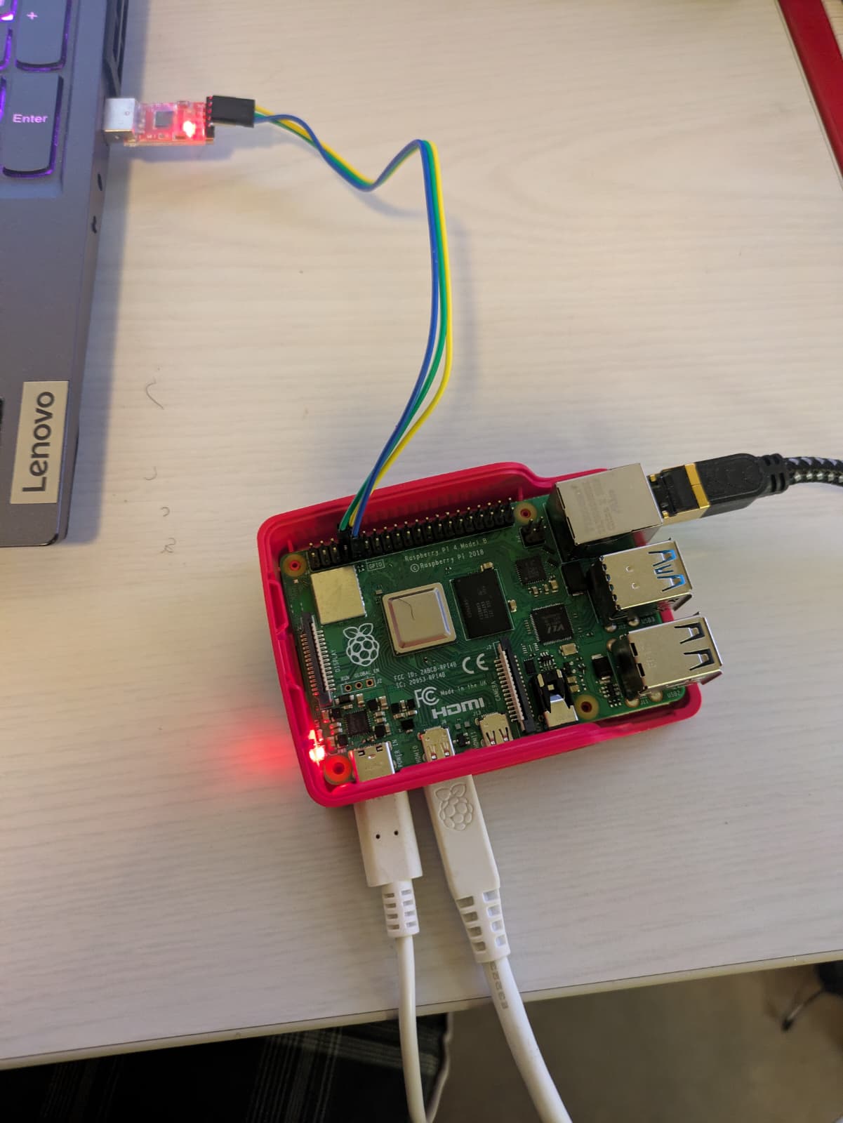
The RPi4 exposes its UART on the 40-pin GPIO header. Use a 3.3V logic level USB to TTL adapter connected as follows:
| USB-TTL wire | RPi4 pin | Function |
|---|---|---|
| GND | Pin 6 | Ground |
| RX | Pin 8 (GPIO14 / TXD) | RPi4 transmits here, adapter receives |
| TX | Pin 10 (GPIO15 / RXD) | Adapter transmits here, RPi4 receives |
| 5V | Do not connect | Would backfeed power |
The TX/RX naming is relative to the device. The RPi4 transmits on its TX pin (GPIO14), so the adapter's RX wire connects there. Getting these crossed produces no output at all — the most common first mistake.
B.2 Installing picocom
sudo apt install picocom
sudo adduser $USER dialout
The dialout group membership is required to access /dev/ttyUSB0 without sudo. Log out and back in after adding the group, or run newgrp dialout in the current terminal as a temporary workaround.
B.3 Opening the console
Plug in the adapter and check which device it appears as:
dmesg | tail -5
# [xxxxx] usb 2-1: cp210x converter now attached to ttyUSB0
Open picocom:
picocom -b 115200 /dev/ttyUSB0
When ready it shows:
picocom v3.1
port is        : /dev/ttyUSB0
baudrate is    : 115200
Terminal ready
To exit: Ctrl+A then Ctrl+X.
The RPi4 GPU firmware, TF-A, and U-Boot all default to 115200 baud. The enable_uart=1 line in config.txt activates the UART on GPIO 14/15, and dtoverlay=disable-bt reassigns it from Bluetooth to the GPIO header.
Part C — Preparing the SD card
C.1 Creating the partition table
The SD card needs two partitions. Create them with cfdisk:
sudo umount /dev/sdb* 2>/dev/null || true
sudo dd if=/dev/zero of=/dev/sdb bs=1M count=16
sudo cfdisk /dev/sdb
The dd command wipes the first 16MB, erasing any existing partition table. Without this, cfdisk can inherit a corrupt layout from a previous use of the card.
Inside cfdisk: select dos label type, create partition 1 as 128MB with type c (W95 FAT32 LBA, 0x0c), create partition 2 with the remaining space as type 83 (Linux), write and quit.
The result:
┌─────────────────────────────────────────────────────────┐
│  /dev/sdb (16GB SD card)                                │
├──────────────────┬──────────────────────────────────────┤
│  /dev/sdb1       │  /dev/sdb2                           │
│  128MB           │  ~15.8GB                             │
│  FAT32 (W95 LBA) │  ext4                                │
│  BOOT            │  rootfs                              │
│                  │                                      │
│  GPU firmware    │  Linux root filesystem               │
│  TF-A BL31       │  kernel + DTB (for SD card boot)     │
│  U-Boot          │  BusyBox / Buildroot system          │
│  config.txt      │                                      │
└──────────────────┴──────────────────────────────────────┘
C.2 Formatting the partitions
sudo mkfs.vfat -F 32 -n BOOT /dev/sdb1
sudo mkfs.ext4 -L rootfs /dev/sdb2
FAT32 is non-negotiable for partition 1. The BCM2711 GPU ROM can only read FAT32. If partition 1 is formatted as anything else, the board will not boot at all.
Part D — Building U-Boot
D.1 Getting the sources
git clone https://gitlab.denx.de/u-boot/u-boot
cd u-boot
git checkout v2023.01
D.2 Configuring for RPi4
make rpi_4_defconfig
make menuconfig
In menuconfig, configure the environment storage location so U-Boot saves its settings to a file on the FAT partition. Settings saved there survive power cycles. Settings that are not saved disappear on the next reboot.
Environment
  → Environment is in a FAT filesystem   [enable]
  → Block device name: mmc
  → Device and partition: 0:1
  → FAT file name: uboot.env
The only partition the GPU firmware can read is the FAT32 boot partition, so the environment file must live there.
D.3 Building
make -j$(nproc)
The output we need is u-boot.bin:
ls -lh u-boot.bin
# u-boot.bin  603K
D.4 Renaming for the GPU
The GPU will not load a file called u-boot.bin. It has a hardcoded search order for kernel images in 64-bit mode, and u-boot.bin is not on that list. The file must be renamed to kernel8.img:
cp u-boot.bin kernel8.img
Part E — Building TF-A
E.1 Getting the sources
git clone https://git.trustedfirmware.org/TF-A/trusted-firmware-a.git
cd trusted-firmware-a
git checkout v2.10.0
E.2 The build command explained
make \
  CROSS_COMPILE=aarch64-linux- \
  PLAT=rpi4 \
  RPI3_PRELOADED_DTB_BASE=0x2600000 \
  PRELOADED_BL33_BASE=0x80000 \
  SUPPORT_VFP=1 \
  DEBUG=1 \
  all
Every parameter matters. Getting any of them wrong produces a failure that is hard to diagnose without understanding what they do.
PLAT=rpi4 selects the RPi4 platform code under plat/rpi/rpi4/. TF-A supports dozens of platforms, each with different hardware initialisation code.
RPI3_PRELOADED_DTB_BASE=0x2600000 is the physical address where the GPU loads the Device Tree before jumping to TF-A. TF-A needs this address to find and patch the DTB, adding PSCI nodes so Linux knows power management services are available. This address must match device_tree_address= in config.txt.
PRELOADED_BL33_BASE=0x80000 is where U-Boot sits in RAM when TF-A starts. After finishing EL3 setup, TF-A jumps to this address. This must match the address where the GPU loads kernel8.img, which defaults to 0x80000 in 64-bit mode. If these two values disagree, TF-A jumps to empty memory and the system hangs silently.
This was the first major debugging trap. The initial TF-A build used
PRELOADED_BL33_BASE=0x20000, copied from documentation that assumed an explicitkernel_address=override inconfig.txt. The GPU was loading U-Boot to0x80000but TF-A was jumping to0x20000. TF-A output appeared perfectly, then silence. No U-Boot, no errors, nothing. One wrong parameter. Forty-five minutes of investigation.
SUPPORT_VFP=1 enables Vector Floating Point in EL3. The Cortex-A72 initialisation code uses VFP registers. Without this flag, TF-A traps on those instructions and crashes.
DEBUG=1 enables serial output from BL31. Without it, TF-A runs completely silently. Always use DEBUG=1 during development.
Always run
make PLAT=rpi4 cleanbefore changing build parameters. TF-A caches objects aggressively. ChangingPRELOADED_BL33_BASEwithout cleaning produces a two-second build that silently reuses the old binary. Thirty minutes were lost to this.
Part F — Assembling the FAT partition
F.1 Copying the files
Mount the FAT partition:
sudo mount /dev/sdb1 /mnt
The partition needs these files:
armstub8.bin          ← TF-A BL31 binary (bl31.bin renamed for GPU firmware)
bcm2711-rpi-4-b.dtb   ← BCM2711 Device Tree
config.txt            ← boot configuration
fixup4.dat            ← GPU memory split configuration
kernel8.img           ← U-Boot (u-boot.bin renamed for GPU firmware)
start4.elf            ← GPU main firmware
Copy the TF-A binary:
sudo cp trusted-firmware-a/build/rpi4/debug/bl31.bin /mnt/armstub8.bin
Copy U-Boot:
sudo cp u-boot/kernel8.img /mnt/
Download the official Raspberry Pi firmware files:
git clone --depth=1 https://github.com/raspberrypi/firmware
sudo cp firmware/boot/start4.elf /mnt/
sudo cp firmware/boot/fixup4.dat /mnt/
sudo cp firmware/boot/bcm2711-rpi-4-b.dtb /mnt/
The rainbow screen mystery. During testing, the board displayed the GPU rainbow splash screen and never proceeded further. TF-A output appeared correctly on serial, proving the GPU was running. But the rainbow never disappeared.
The cause:
bcm2711-rpi-4-b.dtbwas missing from the FAT partition. The GPU firmware expects it to be present for correct initialisation. Without it, firmware behaviour is undefined. In this case it produced a permanent rainbow screen with no error output. Copying the DTB to the partition made it disappear immediately.
F.2 Creating config.txt
sudo tee /mnt/config.txt << 'EOF'
arm_64bit=1
enable_uart=1
dtoverlay=disable-bt
armstub=armstub8.bin
kernel=kernel8.img
device_tree_address=0x2600000
EOF
Each line is load-bearing:
arm_64bit=1: without this the GPU boots in 32-bit mode and TF-A never runs.enable_uart=1: enables GPIO 14/15 as the serial console.dtoverlay=disable-bt: frees the PL011 UART from Bluetooth so U-Boot has a proper serial port.armstub=armstub8.bin: tells the GPU to load TF-A at address0x0and execute it at EL3.kernel=kernel8.img: the U-Boot binary, loaded to0x80000.device_tree_address=0x2600000: where the GPU places the DTB. Must matchRPI3_PRELOADED_DTB_BASEin the TF-A build.
F.3 Unmounting
sudo umount /mnt
sync
Part G — First boot
G.1 Reading the serial output
Insert the SD card and power on the board. The serial console should show:
NOTICE:  BL31: v2.10.0 (debug):v2.10.0
NOTICE:  BL31: Built : 19:56:22, Apr 17 2026
INFO:    Changed device tree to advertise PSCI.
INFO:    ARM GICv2 driver initialized
INFO:    BL31: Initializing runtime services
INFO:    BL31: cortex_a72: CPU workaround for erratum 859971 was applied
WARNING: BL31: cortex_a72: CPU workaround for erratum 1319367 was missing!
INFO:    BL31: cortex_a72: CPU workaround for CVE 2017_5715 was applied
INFO:    BL31: cortex_a72: CPU workaround for CVE 2018_3639 was applied
INFO:    BL31: cortex_a72: CPU workaround for CVE 2022_23960 was applied
INFO:    BL31: Preparing for EL3 exit to normal world
INFO:    Entry point address = 0x80000
INFO:    SPSR = 0x3c9

U-Boot 2023.01 (Apr 17 2026)
DRAM:  948 MiB (effective 1.9 GiB)
RPI 4 Model B (0xb03115)
...
U-Boot>
Reading the output line by line:
Changed device tree to advertise PSCI: TF-A found the DTB at0x2600000and patched it. This is what makes PSCI work.cortex_a72: CPU workaround for erratum 859971 was applied: silicon bug fixed at EL3 before Linux runs.CPU workaround for CVE 2017_5715 was applied: Spectre variant 2 mitigated by TF-A.Entry point address = 0x80000: TF-A jumping to U-Boot at the correct address. If this line appears and U-Boot does not follow, the address is wrong.SPSR = 0x3c9: CPU entering EL2 AArch64 with interrupts masked, the correct state for U-Boot.
The WARNING about erratum 1319367 is harmless. It requires a newer TF-A version to patch and does not affect normal operation.
G.2 Verifying TF-A integration
At the U-Boot prompt, inspect the DTB that TF-A patched:
U-Boot> fdt addr 0x2600000
U-Boot> fdt print /psci
psci {
    cpu_on = <0xc4000003>;
    cpu_off = <0x84000002>;
    cpu_suspend = <0xc4000001>;
    method = "smc";
    compatible = "arm,psci-1.0", "arm,psci-0.2", "arm,psci";
};
This node was not in the original DTB file on the SD card. TF-A BL31 added it at runtime. When Linux boots, it reads this node and knows it can call back into BL31 via SMC instructions for CPU power management. If this node is absent, PSCI services are unavailable and reboot will not work correctly.
G.3 Saving U-Boot environment variables
U-Boot variables set with setenv live only in RAM and disappear on every power cycle. Save them to the FAT partition:
U-Boot> setenv ipaddr 192.168.0.100
U-Boot> setenv serverip 192.168.0.1
U-Boot> setenv kernel_addr_r 0x01000000
U-Boot> setenv fdt_addr_r 0x02600000
U-Boot> setenv kernel_comp_addr_r 0x10000000
U-Boot> setenv kernel_comp_size 0x2000000
U-Boot> saveenv
Saving Environment to FAT... OK
What comes next
With TF-A and U-Boot working, the boot chain foundation is in place. The next articles in this series cover:
- Cross-compiling Linux kernel 6.6 for AArch64 and booting it from the SD card
- Setting up TFTP to load the kernel over the network for faster iteration
- Building a minimal BusyBox root filesystem and mounting it over NFS
- Writing Device Tree overlays for custom hardware
Each of those steps builds directly on what was set up here. The effort invested in understanding the full boot chain pays off every time something breaks, and things do break. Knowing that Entry point address = 0x80000 in the TF-A output is the jump to U-Boot means silence after that line can be diagnosed immediately rather than guessed at.
Lab materials adapted from Bootlin's Embedded Linux training (bootlin.com/training/embedded-linux) — CC BY-SA 3.0