This is Part 5 of the Embedded Linux series. It continues directly from Part 4 where we built a complete BusyBox userspace, set up NFS and TFTP boot, and ended with a fully autonomous system using an initramfs embedded inside the kernel.
Before starting this lab, the initramfs configured in Part 4 was removed. Embedding the rootfs inside the kernel image is useful for a standalone system, but it makes development slower: every change to the rootfs requires a full kernel rebuild. Going back to NFS boot means any file modified on the host is immediately visible on the board without rebuilding anything. For a lab that involves frequent kernel config changes and file additions, NFS is the right workflow.
With a working shell on the RPi4 and NFS serving the rootfs, this lab covers three areas: exploring the Linux device model through /dev and /sys, driving GPIOs through the sysfs interface, and bringing up I2C to communicate with an external sensor. As a bonus, we also got USB audio working using kernel modules.
This is part of an ongoing series based on Bootlin's open-source Embedded Linux training, adapted for the Raspberry Pi 4. Lab data files can be downloaded from bootlin.com/training/embedded-linux.
Part A — Exploring /dev and /sys
A.1 The /dev filesystem
The first exercise is to explore /dev on the running target. This directory contains device files, the Linux mechanism through which userspace programs communicate with kernel drivers.
Three categories of devices are visible on the RPi4:
Terminal devices starting with tty handle text input and output. The console device matches whatever was specified in the console= kernel command line parameter — in our case ttyS1. The ttyAMA0 device is the PL011 UART.
MMC block devices starting with mmcblk represent the SD card and its partitions. mmcblk0 is the full SD card, mmcblk0p1 is the FAT32 boot partition, and mmcblk0p2 is the ext4 rootfs partition.
A.2 The /sys filesystem
The /sys filesystem exposes the kernel's internal view of the hardware. It is organized by subsystem rather than by device file.
/sys/class/net shows all network interfaces. Checking /sys/class/net/eth0/speed confirms a gigabit connection. /sys/class/net/eth0/address shows the MAC address without needing ifconfig or ip.
/sys/bus/mmc/devices shows the SD card and exposes useful properties: the serial number, the product name, and the preferred erase size. These are the kind of details a production system might log at startup for diagnostics.
Part B — Driving GPIOs
B.1 Enabling the GPIO sysfs interface
The GPIO sysfs legacy interface requires three kernel config options:
CONFIG_GPIO_SYSFS=y
CONFIG_DEBUG_FS=y
CONFIG_DEBUG_FS_ALLOW_ALL=y
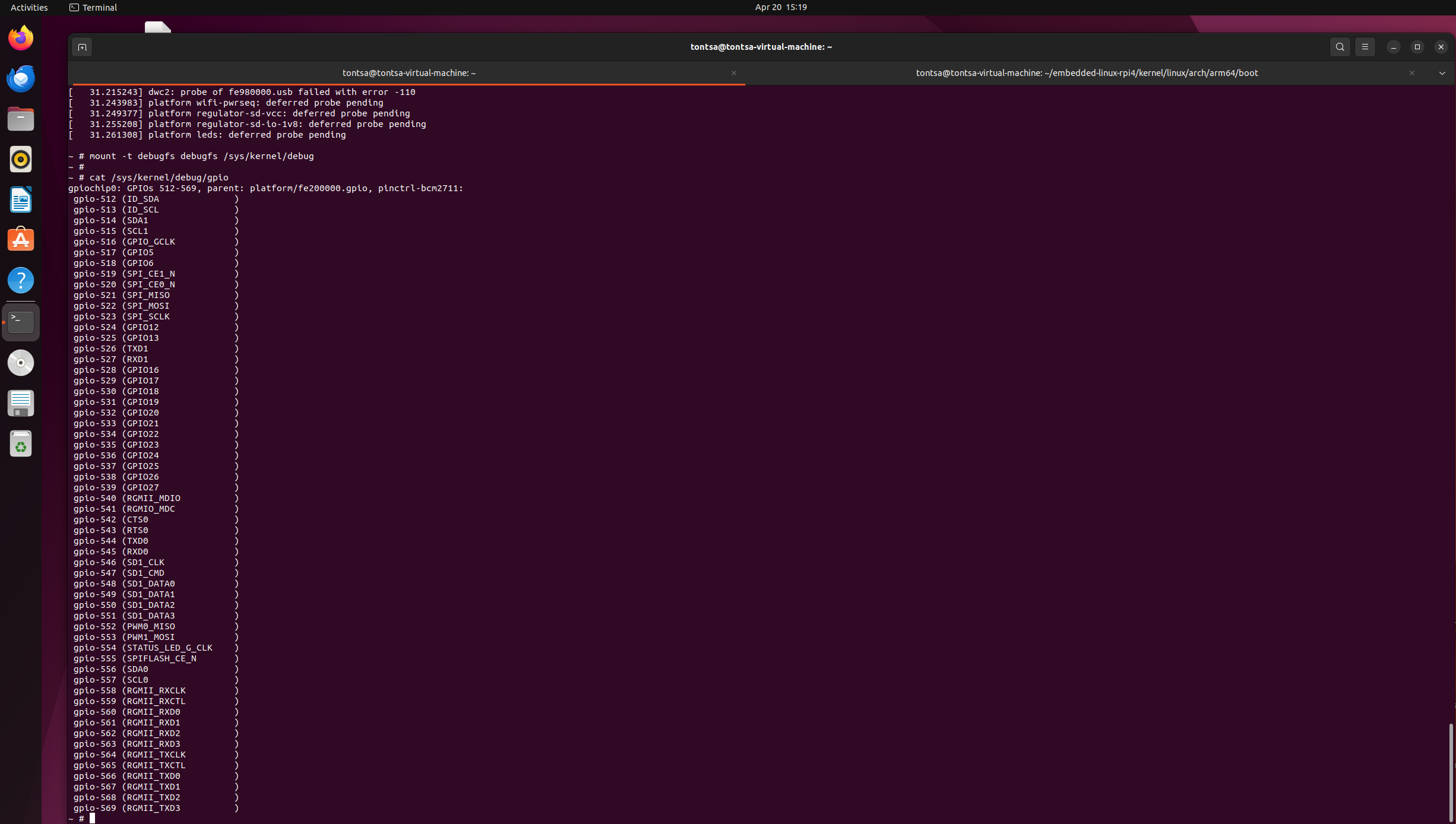
These were enabled in menuconfig. After rebuilding and rebooting, the debugfs filesystem was mounted:
mount -t debugfs debugfs /sys/kernel/debug
cat /sys/kernel/debug/gpio
The output showed the BCM2711 GPIO chip with pins 512 to 569. The numbering offset of 512 comes from the kernel's dynamic GPIO number allocation. GPIO21 on the 40-pin header appears as gpio-533 in the kernel.
B.2 Controlling a GPIO pin
The lab exercise connects a jumper wire to a GPIO pin and reads its state.
Export GPIO21 (kernel number 533):
cd /sys/class/gpio
echo 533 > export
echo in > gpio533/direction
cat gpio533/value
With the pin floating or connected to GND the value reads 0. Connecting the pin to the 3.3V rail (pin 1 on the header) changes the value to 1. Freeing the pin:
echo 533 > unexport
This is the legacy GPIO interface. It works but is being replaced by the character device interface (/dev/gpiochipX) in modern Linux. For now it demonstrates the fundamental concept: hardware state is readable and writable through the filesystem.
Part C — Customizing the Device Tree for I2C
C.1 Why I2C1 is not visible by default
Running i2cdetect -l on the target shows only two I2C buses:
i2c-1    fef09500.i2c    I2C adapter
i2c-0    fef04500.i2c    I2C adapter
These are internal Broadcom STB controllers used by the VideoCore firmware. The BCM2835 I2C1 controller at fe804000, which is connected to GPIO2 (SDA) and GPIO3 (SCL) on the 40-pin header, is not present.
Tracing through the Device Tree file hierarchy explains why:
bcm283x.dtsi        defines i2c@7e804000, status = "disabled"
bcm2711.dtsi        adds compatible string, does not enable it
bcm2711-rpi-4-b.dts never mentions i2c1
The hardware exists and is fully functional. The software simply has not been told to use it.
C.2 The Device Tree file hierarchy
Finding the right files to modify required understanding the include chain. The arm64 wrapper file at:
arch/arm64/boot/dts/broadcom/bcm2711-rpi-4-b.dts
Contains only a single line:
#include "arm/broadcom/bcm2711-rpi-4-b.dts"
The real board file lives under arch/arm/boot/dts/broadcom/. This file includes bcm2711.dtsi which includes bcm283x.dtsi where i2c1 is defined. The DTB that U-Boot loads is built from the arm64 tree, which delegates to the arm tree through includes.
C.3 Creating a custom Device Tree file
The Bootlin lab teaches the correct approach: never modify the standard board file maintained by kernel developers. Instead create a new file that includes the standard one and patches only what is needed. The lab does this for the BeaglePlay with a file that looks like this:
/dts-v1/;
#include "k3-am625-beagleplay.dts"

&wkup_i2c0 {
    status = "okay";
    /delete-property/ pinctrl-0;
};
We follow exactly the same pattern for the RPi4, creating bcm2711-rpi-4-b-custom.dts:
/dts-v1/;
#include "bcm2711-rpi-4-b.dts"

&i2c1 {
    status = "okay";
    /delete-property/ pinctrl-0;
};
Three things are happening here. /dts-v1/ declares this is a Device Tree source file. #include "bcm2711-rpi-4-b.dts" pulls in the entire standard RPi4 Device Tree — every peripheral, every clock, every pin definition. &i2c1 is a reference to the i2c1 label defined in bcm283x.dtsi, and the block inside patches that node: status = "okay" overrides the default "disabled", and /delete-property/ pinctrl-0 removes the existing pin mux reference.
Why /delete-property/ first? The lab deliberately starts with
/delete-property/ pinctrl-0to demonstrate what happens when a device has no associated pin definitions. After rebooting with this DTB,i2cdetect -lshows I2C1 as a new bus — proving the controller is enabled. But runningi2cdetect -r 1produces a flood ofi2c transfer timed outerrors even with nothing connected. The I2C controller is alive but the GPIO pins are not configured for I2C function. They are floating in an undefined state. The bus cannot complete any transaction. This is the lab's way of showing that enabling a peripheral in the Device Tree is not enough on its own — the pin mux must also be correct.
After observing this behaviour, the fix is simply to remove the /delete-property/ line entirely, leaving the node as:
/dts-v1/;
#include "bcm2711-rpi-4-b.dts"

&i2c1 {
    status = "okay";
};
This is enough on RPi4. The GPU firmware configures GPIO2 and GPIO3 for I2C function during boot before Linux even starts, so the pin mux is already in the correct state when the kernel loads the Device Tree. Setting status = "okay" is the only change needed. After rebuilding the DTB and rebooting, the timeouts disappear entirely and I2C1 is fully functional.
Add the custom DTB to the arm64 Makefile:
# In arch/arm64/boot/dts/broadcom/Makefile
dtb-$(CONFIG_ARCH_BCM2835) += bcm2711-rpi-4-b.dtb \
                              bcm2711-rpi-4-b-custom.dtb \
Rebuild DTBs, copy to TFTP, reboot with the custom DTB:
U-Boot> tftp 0x02600000 bcm2711-rpi-4-b-custom.dtb
After enabling CONFIG_I2C_BCM2835=y and rebuilding the kernel, I2C1 appeared:
i2c-1 bcm2835 (i2c@7e804000) I2C adapter
C.4 Detecting the MAX30102 sensor
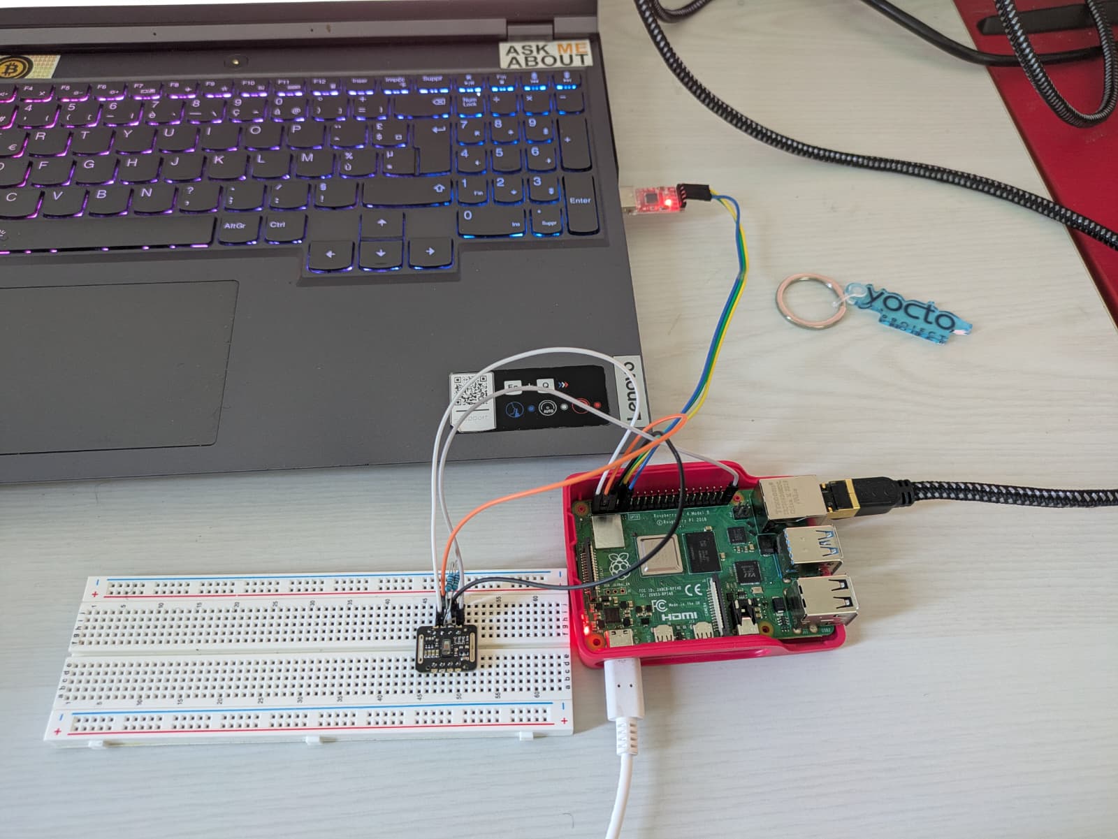
With I2C1 working, scanning the bus immediately found the MAX30102 heart rate sensor:
i2cdetect -r 1
     0  1  2  3  4  5  6  7  8  9  a  b  c  d  e  f
50: -- -- -- -- -- -- -- 57 -- -- -- -- -- -- -- --
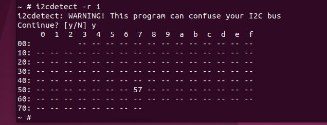
Address 0x57 confirmed. The sensor is wired with SDA on GPIO2 (pin 3) and SCL on GPIO3 (pin 5), VCC to 3.3V.
Part D — Getting USB working
D.1 The RPi4 USB architecture
Getting USB audio working required understanding how USB works on the RPi4. Unlike most ARM SoCs where the USB controller is integrated directly into the SoC, the RPi4 takes a different approach. The four full-size USB 3.0 ports are driven by a separate VIA VL805 xHCI chip that sits on a PCIe bus. This means USB depends on PCIe working first.
The full driver chain from hardware to working USB port is:
BCM2711 PCIe controller (fd500000)
    ↓
VL805 xHCI chip (PCI device 1106:3483)
    ↓
USB host controller
    ↓
USB devices (speaker, flash drive, hub)
Each layer requires its own kernel driver. All four were missing from our minimal kernel configuration.
D.2 The four missing drivers explained
CONFIG_PCIE_BRCMSTB is the PCIe host controller driver for the BCM2711. Without it the PCIe bus is never initialized, the VL805 chip is never discovered, and the USB ports are completely dead. The kernel does not even know the chip exists. Enabling this option made the PCIe link come up at 5.0 GT/s and the VL805 appeared as PCI device 0000:01:00.0.
CONFIG_USB_XHCI_PCI is the xHCI driver for USB controllers connected via PCI rather than directly on the SoC bus. xHCI (eXtensible Host Controller Interface) is the standard interface for USB 3.0 host controllers. Even though the VL805 was now visible on the PCIe bus, without this driver the kernel had nothing to bind to it. The symptom was pci 0000:01:00.0: deferred probe pending in dmesg. This option was set to m (module) rather than y (built-in), which meant the driver existed but was never loaded since we have no module infrastructure yet. Changing it to y should have fixed the issue — but it did not, because of the next dependency.
CONFIG_BCM2835_MBOX is the mailbox driver for the BCM2835 hardware mailbox, the communication channel between the ARM cores and the VideoCore GPU. On the RPi4 the GPU manages several hardware resources including the VL805 chip. Before the xHCI driver can initialize the VL805, the GPU needs to load firmware into it via the mailbox interface. Without the mailbox driver this communication path does not exist. This option also had a practical consequence during debugging: CONFIG_RASPBERRYPI_FIRMWARE depends on it, so when BCM2835_MBOX was not set, the firmware driver option was completely invisible in menuconfig — it did not appear even when searched.
CONFIG_RASPBERRYPI_FIRMWARE is the Raspberry Pi firmware driver. It provides the interface between Linux and the VideoCore GPU firmware running on the RPi4. Among other things it handles resetting and initializing the VL805 xHCI chip at boot. Without this driver the VL805 stayed in a deferred probe pending state indefinitely because the GPU initialization sequence never completed. This was the final missing piece.
CONFIG_RASPBERRYPI_POWER is the power domain driver for the Raspberry Pi. It depends on CONFIG_RASPBERRYPI_FIRMWARE and manages the power domains exposed by the GPU firmware, including the USB power domain. Without it certain peripherals controlled by the GPU power management may not initialize correctly. It was enabled alongside the firmware driver as a direct dependency.
D.3 USB devices detected
After enabling all four options, rebuilding the kernel, and rebooting, lsusb showed:
Bus 001 Device 001: ID 1d6b:0002  xhci-hcd xHCI Host Controller
Bus 001 Device 005: ID 4c4a:4155  Jieli Technology UACDemoV1.0
Bus 001 Device 003: ID 05dc:c75c  Lexar USB Flash Drive
Bus 001 Device 002: ID 2109:3431  USB2.0 Hub
Bus 002 Device 001: ID 1d6b:0003  xhci-hcd xHCI Host Controller
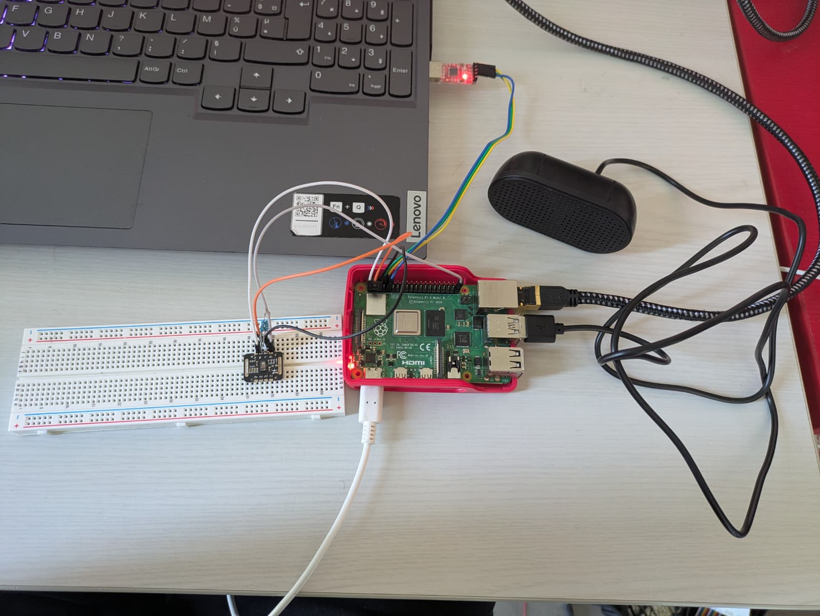
The USB speaker (Jieli Technology UACDemoV1.0) is visible on Bus 001. The USB audio driver setup continues in the next session.
 ---
---
Part E — Kernel modules and USB audio
E.1 Kernel modules
Until now every driver has been compiled directly into the kernel image (=y). The USB audio driver is the first one we compile as a loadable module (=m). This is deliberate — the lab uses it to introduce the kernel module workflow.
The difference between built-in and module:
- Built-in (
=y): the driver is part ofImage.gz. It initializes at boot whether or not the hardware is present. - Module (
=m): the driver is compiled as a separate.kofile. It is loaded on demand, either manually withmodprobeor automatically by the kernel when it detects matching hardware.
Set CONFIG_SND_USB_AUDIO=m in menuconfig, then compile the modules separately from the kernel image:
make -j$(nproc) modules
make modules_install INSTALL_MOD_PATH=/home/tontsa/embedded-linux-rpi4/nfsroot
make modules compiles all =m options into .ko files. make modules_install copies them into the nfsroot under /lib/modules/6.6.134/. Since the rootfs is served over NFS the modules are immediately visible on the target without any additional copying.
A recurring trap. Running
make Image.gzaftermake modulestriggered an interactive configuration session that silently disabledCONFIG_SERIAL_8250_BCM2835AUX— the ttyS1 console driver — along with several USB and audio options. The correct approach is to runmake olddefconfiginstead of answering the interactive prompts. This applies all new symbols with their default values automatically without touching existing settings. After any interactive session, always verify withgrep "CONFIG_SERIAL_8250_BCM2835AUX" .configbefore rebuilding.
Save the working configuration after every successful boot:
make savedefconfig
cp defconfig ~/embedded-linux-rpi4/rpi4-custom-defconfig
E.2 Loading the USB audio module
After rebooting with the new kernel and modules installed, the module is loaded manually:
modprobe snd-usb-audio
Output:
[ 368.253667] usbcore: registered new interface driver snd-usb-audio
Plugging in the USB speaker after loading the module caused the driver to bind to the device immediately. The /dev/snd/ directory populated with three entries:
ls /dev/snd/
controlC0  pcmC0D0p  timer
controlC0is the mixer control interface for card 0pcmC0D0pis the PCM playback device (card 0, device 0, playback)timeris the ALSA timer
Reading the card information directly from the kernel:
cat /proc/asound/cards
 0 [UACDemoV10     ]: USB-Audio - UACDemoV1.0
                      Jieli Technology UACDemoV1.0 at usb-0000:01:00.0-1.1, full speed
And the supported audio format:
cat /proc/asound/card0/stream0
Playback:
  Format: S16_LE
  Channels: 2
  Rates: 48000
  Bits: 16
  Channel map: FL FR
The speaker supports 16-bit stereo at 48 kHz. The driver is working correctly. Audio playback testing requires aplay from the alsa-utils package which will be cross-compiled in a later lab.
E.3 Autoloading the module at boot
Rather than loading the module manually after every reboot, add it to the startup script:
# In /etc/init.d/rcS
modprobe snd-usb-audio
From this point on the USB audio driver loads automatically at boot and the speaker is ready as soon as the system starts.
Part F — Declaring the MAX30102 in the Device Tree
The MAX30102 sensor and wiring
The MAX30102 is a pulse oximetry and heart rate monitoring sensor from Maxim Integrated. It contains two LEDs, one red and one infrared, and a photodetector. By shining these LEDs through the skin and measuring how much light is absorbed, the sensor can detect blood oxygen saturation (SpO2) and heart rate. It is the same type of sensor found in fitness trackers and medical pulse oximeters.
The sensor communicates over I2C and has a fixed address of 0x57. It also has an INT pin that goes low when new data is available in the FIFO buffer, which the driver uses to trigger data reads without polling.
The sensor was wired to the RPi4 40-pin header as follows:
| MAX30102 pin | RPi4 pin | Function |
|---|---|---|
| VCC | Pin 1 | 3.3V power |
| GND | Pin 6 | Ground |
| SDA | Pin 3 (GPIO2) | I2C1 data |
| SCL | Pin 5 (GPIO3) | I2C1 clock |
| INT | Pin 18 (GPIO24) | Interrupt, active low |
I2C is an open-drain bus, meaning the SDA and SCL lines need pull-up resistors to function correctly. Without them the lines float and the bus cannot communicate. A 4.7 kΩ resistor was added between SDA and 3.3V, and another between SCL and 3.3V. Most MAX30102 breakout boards include these resistors on the module itself, but if yours does not, they must be added externally on the breadboard.
The INT pin connection is mandatory. The mainline MAX30102 driver does not support polling mode. It requires a hardware interrupt line to be declared in the Device Tree or the probe will fail with no valid irq defined.
F.1 Why the driver alone is not enough
After enabling CONFIG_MAX30102=y in menuconfig and rebuilding the kernel, the driver was compiled directly into the kernel image and initialized at boot. But i2cdetect -r 1 still showed 57 rather than UU. The driver was present and running but had nothing to bind to. This is the same situation the Bootlin lab demonstrates with the Nunchuk: a driver being present in the kernel does not mean the kernel knows there is a matching device on the bus. The device must be declared in the Device Tree with a compatible string that matches what the driver expects.
Checking /sys/bus/i2c/drivers/ confirmed the max30102 directory existed but contained no device symlink. The driver was registered and waiting, but with nothing to bind to.
F.2 Adding the interrupt line
Before declaring the sensor, the MAX30102 driver source was checked. It requires a hardware interrupt line — there is no fallback polling mode. The INT pin on the MAX30102 breakout board was not connected, which would have caused the probe to fail with no valid irq defined.
The INT pin was wired to GPIO24 (pin 18 on the 40-pin header). This pin was confirmed free from the earlier cat /sys/kernel/debug/gpio output.
F.3 The updated Device Tree
The custom DTS was updated to declare the sensor with its interrupt:
/dts-v1/;
#include "bcm2711-rpi-4-b.dts"

/ {
    model = "TA Embedded RPi4 Lab";
};

&i2c1 {
    status = "okay";

    max30102: max30102@57 {
        compatible = "maxim,max30102";
        reg = <0x57>;
        maxim,red-led-current-microamp = <7000>;
        maxim,ir-led-current-microamp = <7000>;
        interrupt-parent = <&gpio>;
        interrupts = <24 2>;
    };
};
A few notes on each property:
compatible = "maxim,max30102" must match exactly what the driver registers. The kernel uses this string to decide which driver to bind to which device.
reg = <0x57> is the I2C address. If this does not match the physical address of the device on the bus, the driver will probe but fail to communicate.
maxim,red-led-current-microamp and maxim,ir-led-current-microamp set the LED drive current. The driver defaults to 7 mA if these are absent, but declares them explicitly to avoid the info messages in dmesg.
interrupts = <24 2> means GPIO24 with falling edge trigger, matching the driver's IRQF_TRIGGER_FALLING requirement.
The model property at the root node overrides the standard board name, changing what appears in the first kernel boot message and in /sys/firmware/devicetree/base/model.
F.4 Driver probe result
After rebuilding the DTB and rebooting:
i2cdetect -r 1: address 0x57 shows UU
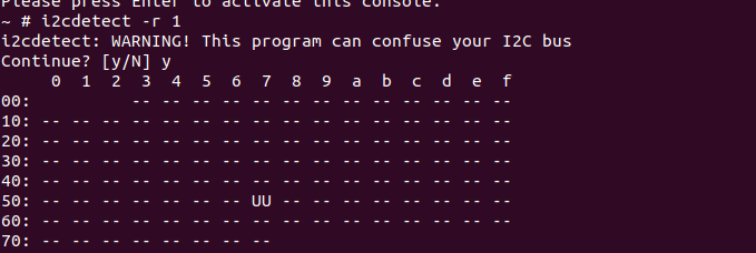 `UU` confirms the driver claimed the device. The IIO subsystem registered it:
ls /sys/bus/iio/devices/
iio:device0

cat /sys/bus/iio/devices/iio:device0/name
max30102
Temperature readings were immediately accessible:
cat /sys/bus/iio/devices/iio:device0/in_temp_raw
463
The raw value of 463 corresponds to approximately 28.9°C using the MAX30102 temperature formula (value × 0.0625°C).
F.5 The kernel crash
Reading in_temp_raw a second time triggered a kernel NULL pointer dereference in max30102_interrupt_handler at __bitmap_weight. This is a known bug in the mainline max30102 driver: an interrupt fires before the IIO buffer is fully initialized, causing a NULL dereference in the bitmap weight calculation used by the FIFO handler.
The crash does not affect the temperature channel which bypasses the interrupt path. The intensity channels (red and infrared) require the IIO buffer interface which is where the crash occurs. This is a driver bug to investigate in a later lab.
Part G — Committing the changes
G.1 The kernel contribution workflow
The Bootlin lab ends each hardware section by committing the custom Device Tree changes and generating a patch. This is not just housekeeping — it teaches the exact workflow used to contribute changes to the Linux kernel.
Every change submitted to the mainline kernel goes through this process: create a branch, commit with a descriptive message and a Signed-off-by line, generate a patch file, send it to the maintainer. The Signed-off-by line is a legal statement that the author wrote the code and has the right to submit it under the kernel's open source license.
G.2 Creating the branch and patch
git config --global user.email "frankapala75@gmail.com"
git config --global user.name "FrankApala"

git checkout -b ta-embedded-rpi4
git add arch/arm64/boot/dts/broadcom/bcm2711-rpi-4-b-custom.dts
git commit -s -m "arm64: dts: bcm2711: Add custom RPi4 DTS for TA Embedded lab"
git format-patch stable/linux-6.6.y
This produced 0001-arm64-dts-bcm2711-Add-custom-RPi4-DTS-for-TA-Embedde.patch — a self-contained file that can be applied to any clean 6.6 kernel tree to reproduce the exact custom DTS.
Creating the branch changed the kernel version string from 6.6.134-dirty to 6.6.134-00001-g86719fc427b1-dirty. The modules directory name changed accordingly. The old lib/modules/6.6.134-dirty directory was removed from the nfsroot after reinstalling modules under the new version name.
G.3 Final verification
After rebooting with the rebuilt kernel:
uname -r
6.6.134-00001-g86719fc427b1-dirty

cat /sys/firmware/devicetree/base/model
TA Embedded RPi4 Lab

i2cdetect -r 1
# 0x57 shows UU — MAX30102 driver bound

lsmod
# snd_usb_audio and dependencies loaded
What this lab teaches
The Device Tree is not documentation. It is executable configuration. Setting status = "okay" in two lines enables a hardware controller the kernel would otherwise ignore entirely. Declaring a sensor with the correct compatible string and reg address is what causes the kernel to load the right driver and bind it to the right device. Without the Device Tree declaration, the driver and the hardware exist independently and never meet.
The USB bring-up demonstrated a common pattern in embedded Linux debugging: a deferred probe is rarely the root problem. It is a symptom of a missing dependency earlier in the chain. Following the chain backwards, one driver at a time, is how these problems get solved.
The module workflow showed why the distinction between =y and =m matters in practice. A built-in driver initializes at boot whether or not the hardware is present. A module loads on demand, which is useful for development and for hardware that may not always be connected.
The git patch workflow is the actual contribution process used by the Linux kernel community. Learning it here on a lab exercise is direct preparation for submitting real changes upstream.
What was done
✓ Removed initramfs, returned to NFS boot for rapid iteration
✓ Explored /dev and /sys device model
✓ Enabled GPIO sysfs interface and debugfs
✓ Controlled GPIO21 via sysfs legacy interface
✓ Created custom Device Tree file for I2C1
✓ Learned the /delete-property/ lesson hands-on
✓ Enabled BCM2835 I2C1 controller on GPIO2/GPIO3
✓ Detected MAX30102 sensor at address 0x57
✓ Enabled PCIe, xHCI, mailbox, and RPi firmware drivers
✓ USB host controller working, all USB devices detected
✓ Compiled snd-usb-audio as a kernel module
✓ Installed modules to nfsroot via modules_install
✓ USB speaker recognized: S16_LE stereo 48kHz
✓ Module autoloaded at boot via rcS
✓ MAX30102 declared in Device Tree with interrupt on GPIO24
✓ Driver probed successfully, IIO device registered
✓ Temperature reading working: ~28.9°C
✓ Custom model name: TA Embedded RPi4 Lab
✓ Changes committed on branch ta-embedded-rpi4
✓ Patch generated: 0001-arm64-dts-bcm2711-...patch
Lab materials adapted from Bootlin's Embedded Linux training (bootlin.com/training/embedded-linux), CC BY-SA 3.0